Display Max6675 Thermocouple Readings on 1602 Lcd Arduino
In this tutorial, nosotros will learn how to interface MAX6675 thermocouple module with Arduino and how to apply it to measure temperature. The guide includes a brief introduction of the module with its pinout and connection diagram with Arduino. Additionally, we will show you two Arduino sketches where nosotros will be able to admission the temperature readings from this module and brandish them on the Serial Monitor as well as on an OLED.
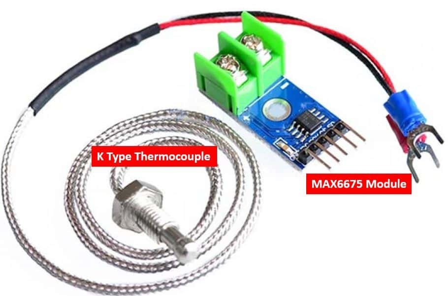
MAX6675 Thermocouple
The MAX6675 module comes with a 1000-type thermocouple along with a driver and amplifier used to mensurate temperature in the range of 0°C to 1024°C. This is i of the ideal choices for measuring higher temperature readings which the other temperature sensors such as LM35 and others. This module consists of the MAX6675 chip which measures the temperature via the K-type thermocouple. The module uses an SPI interface to communicate with the microcontroller and transfer the output temperature readings.
Beneath you tin view the specifications of this module:
- 12- bit resolution
- Accurateness of 8 LSBs
- Resolution of 0.25°C
- Operating Voltage is 5V
- Operating Electric current is 50mA
Thermocouple
The thermocouple is made with 2 different fabric wires. One end of these wires is continued together for making the junction. This junction is placed in that specific environment or object whose temperature we want to measure. When the temperature is changed and so ii different materials start to deform, as a issue, the resistance is changed. Actually, its output is a millivolt point whose voltages are changed when resistance is changed. This change in voltages could be measured hands with the aid of thermocouples.
Working Principle
The working principle of Thermocouple is based on the Seebect result. Co-ordinate to Seebeck, when two unlike metals are connected together for making ii junctions then electromotive force would be developed at two junctions. The amount of this force would exist dissimilar with metal material combinations.
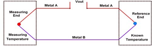
According to the figure above, 2 unlike metals such as metal A and B are connected together for making two junctions. They are called 'measuring finish' and 'reference terminate'. Remember, two junctions are necessary for making whatsoever thermocouple. Temperature of the reference stop is known only the measuring terminate is unknown. When this unknown temperature terminate is placed at that place where nosotros want to measure out the temperature. In this condition, if both ends would exist at the same temperature level then in that location would be no EMF generated. So the internet current in the whole circuit would be also zero.
Similarly, if both ends are at different temperature level and then the EMF would generate and current will be also flowing in the whole circuit. The value of this EMF or electric current too depends on thermocouple metal material every bit well every bit the temperature of both ends. Past measuring the value of this current or EMF the user can easily find out the temperature of that specific place.
There are eight different types of thermocouples currently in the marketplace with respect to their material. We use One thousand Type Thermocouple with MAX6675 module. These K-type thermocouples (Nickel-Chromium / Nickel-Alumel) are less costly, more authentic, more reliable, and the most common type thermocouple. It has a wide range of temperatures such as –454 to ii,300F.
Pinout MAX6675
The diagram below shows the pinout of MAX6675 module:

It consists of a total of seven pins where ii are used to connect the thermocouple positive and negative leads, 3 for the SPI interface, and two for the power and footing.
| Pin Name | Office |
|---|---|
| GND | This is the ground pivot of the module. |
| VCC | This is the VCC pin used to supply power to the module in the range of 3-5.5V |
| SCK | This is the SPI clock pivot. |
| CS | This is the SPI Scrap select pin. |
| SO | This is the serial output pin (information out). |
| Thermocouple+ (Th+) | This is where we will connect the positive lead of the thermocouple. |
| Thermocouple- (Th-) | This is where we will connect the negative atomic number 82 of the thermocouple. |
Interfacing MAX6675 Thermocouple with Arduino
We will require the following components for this projection.
Required Components:
- Arduino
- MAX6675 module with thermocouple
- Connecting Wires
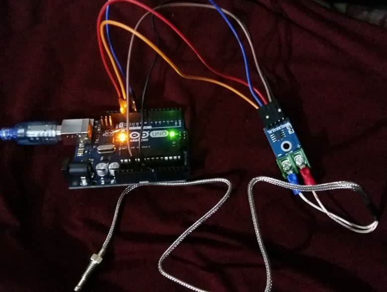
Gather the devices every bit shown in the schematic diagram beneath:
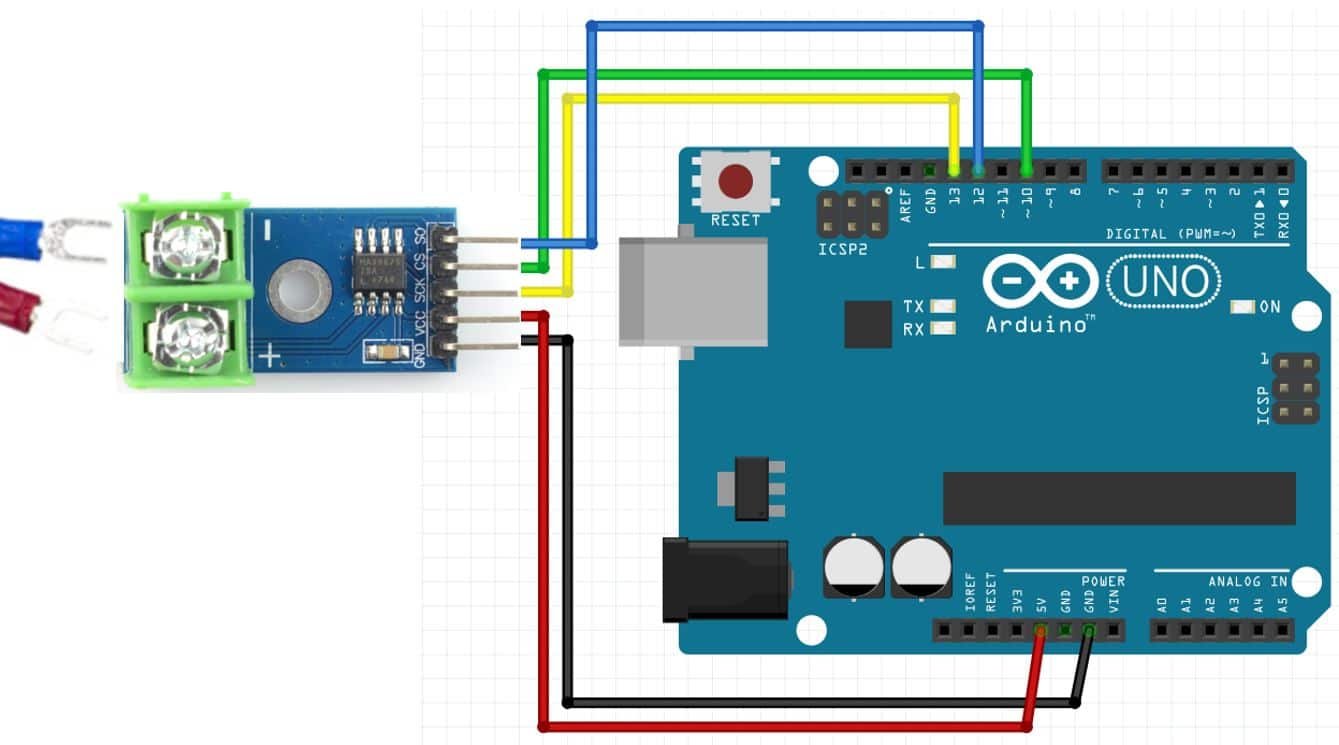
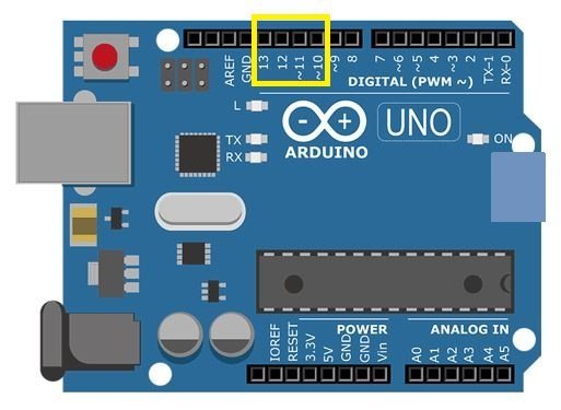
We will connect v pins of the MAX6675 module with Arduino. These include the VCC, GND, SCK, CS and SO pins present on the same side. The VCC will be connected with the 5V pivot from the Arduino. GND of both the devices volition be in common. The default SPI GPIO pins of Arduino are being used to connect with each of the remaining SPI terminals of the MAX6675 module. The effigy beneath shows the default SPI pins of Arduino.
The table below shows the connections between Arduino and the MAX6675 module:
| Arduino | MAX6675 |
| GND | GND |
| 5V | VCC |
| GPIO13 | SCK |
| GPIO10 | CS |
| GPIO12 | SO |
Now follow the connections between the two devices and connect them appropriately. We have used the same connections as specified above. All devices will have their grounds in common.
The thermocouple will be connected at the TH+ and Th- terminals.
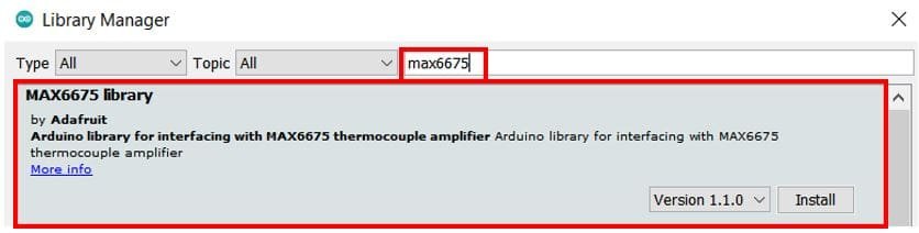
Installing MAX6675 Thermocouple Library
We have an Arduino library for MAX6675 which can be easily used to get values of temperature. Now let's meet how to install the MAX6675 library in Arduino. This library is provided by Adafruit.
To install the library, we will utilise the Arduino Library Manager. Open your Arduino IDE and go to Sketch > Include Libraries > Manage Libraries. Type 'max6675' in the search bar and install the latest version.
Arduino Sketch: Accessing Temperature Readings
Open your Arduino IDE and go toFile > New. A new file volition open. Copy the code given below in that file and salve it.
This lawmaking will apply max6675.h library provided by Adafruit. We will display the temperature (degree Celsius) in the Serial Monitor.
#include "max6675.h" int And then = 12; int CS = ten; int sck = 13; MAX6675 module(sck, CS, So); void setup() { Serial.begin(115200); } void loop() { float temperature = module.readCelsius(); Serial.print("Temperature: "); Serial.impress(temperature); Serial.println(F("°C ")); delay(grand); } How the Code Works?
Nosotros will start off by including the MAX6675 library that we previously installed.
#include "max6675.h" Then we will create iii integer variables each to hold the GPIO pins connected with the SPI pins: SO, SCK and CS. We accept used the Arduino default SPI pins.
int Then = 12; int CS = 10; int sck = 13; Next nosotros will create an instance of MAX6675 chosen module() and pass the sck, CS and And then variables as parameters inside it.
MAX6675 module(sck, CS, SO); Inside the setup() office, we will initialize the serial communication with the baud rate of 115200
void setup() { Serial.begin(115200); } Within the loop() role, we will first obtain the temperature past readCelsius() method on the module instance and save the reading in a floating variable called 'temperature.' This will get printed in the serial monitor along with its unit of measurement afterwards a delay of every one 2nd.
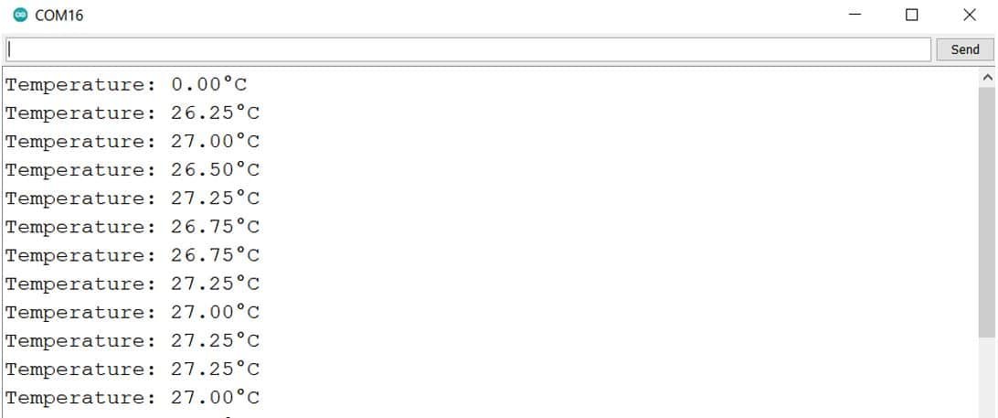
void loop() { float temperature = module.readCelsius(); Serial.print("Temperature: "); Serial.impress(temperature); Serial.println(F("°C ")); delay(1000); } Sit-in
Now upload the Arduino sketch to the Arduino board. Choose the right board and COM port before uploading your lawmaking to the Arduino board. Go to Tools > Board and select Arduino Module.

Side by side, go to Tools > Port and select the appropriate port through which your board is continued.
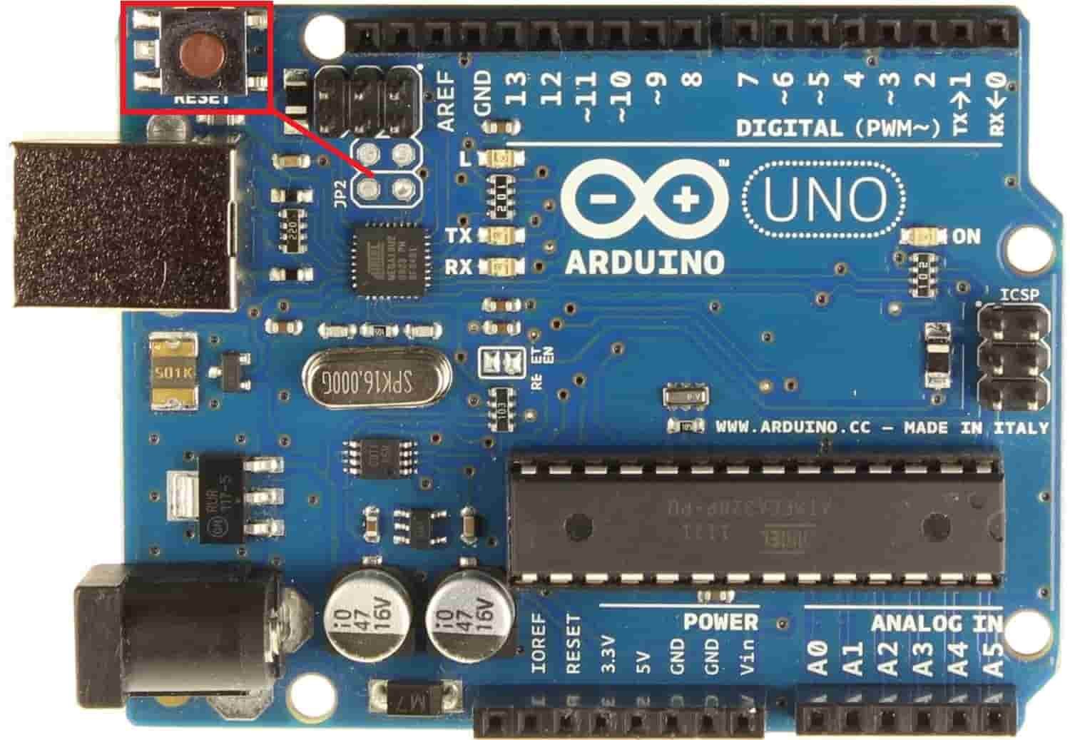
Click on the upload push button to upload the code into the Arduino board. Subsequently you lot have uploaded your code to the board, press its RESET push button.
Now open the serial monitor in Arduino IDE, you will come across temperature readings getting displayed after every 1 2nd.
Arduino Display MAX6675 Thermocouple Readings on OLED
In this section, we will meet how to display the temperature readings of MAX6675 on a 0.96 SSD1306 OLED display using Arduino IDE and Arduino.
Installing SSD1306 OLED Library in Arduino IDE
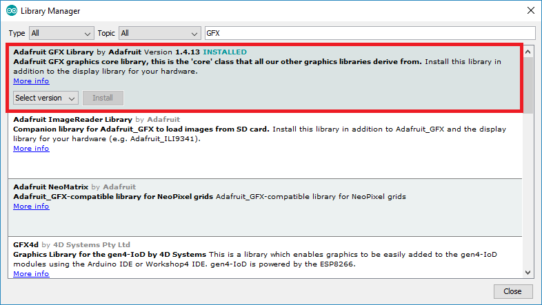
To utilize the OLED display in our projection, we have to install the Adafruit SSD1306 OLED library in Arduino IDE. Follow the steps beneath to successfully install it.
Open Arduino IDE and click onSketch > Library > Manage Libraries. Type 'SSD1306' in the search tab and install the Adafruit SSD1306 OLED library.

We will also require the Adafruit GFX library which is a dependency for SSD1306. Blazon 'Adafruit GFX' in the search tab and install information technology equally well.
You may similar this in-depth guide on OLED interfacing with Arduino:
- OLED Display Interfacing with Arduino – Brandish Text, Draw shapes and Images
Schematic – OLED with Arduino and MAX6675 Thermocouple
This section shows how to connect an Arduino lath with MAX6675 and an OLED display. Follow the connections equally described in the 2 tables below.
The tables below evidence the terminals of the iii devices which should be connected together.
| OLED Display | Arduino |
| VCC | 5V |
| GND | GND |
| SCL | A5 |
| SDA | A4 |
| Arduino | MAX6675 Thou-type thermocouple |
| GND | GND |
| 5 V | VCC |
| GPIO10 | CS |
| GPIO12 | SO |
| GPIO13 | SCK |
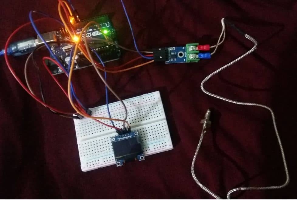
Get together the circuit as shown in the schematic diagram below:
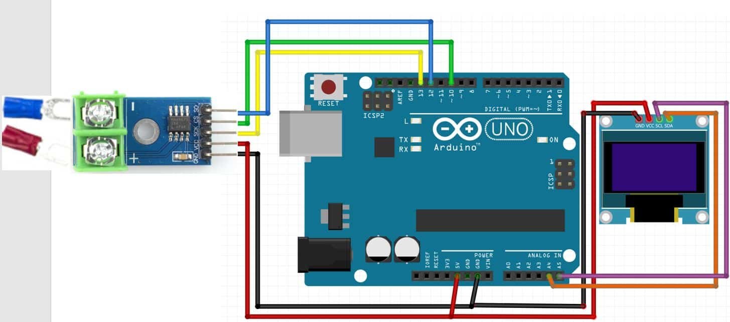
Nosotros will connect the VCC terminal of the OLED display with 5V which will be in common with the Arduino board and MAX6675 VCC. SCL of the brandish will be continued with the SCL pin of the Arduino board and the SDA of the display will exist connected with the SDA of the Arduino.
Arduino Sketch to Display MAX6675 Readings on OLED
Copy the following code to your Arduino IDE and upload it to the Arduino after assembling the above circuit diagram.
#include "max6675.h" #include <Wire.h> #include <Adafruit_GFX.h> #include <Adafruit_SSD1306.h> int SO = 12; int CS = 10; int sck = xiii; MAX6675 module(sck, CS, SO); Adafruit_SSD1306 brandish = Adafruit_SSD1306(128, 64, &Wire, -i); void setup() { Serial.begin(115200); brandish.brainstorm(SSD1306_SWITCHCAPVCC, 0x3C); if(!display.begin(SSD1306_SWITCHCAPVCC, 0x3C)) { Serial.println(F("SSD1306 allocation failed")); for(;;); } delay(2000); display.clearDisplay(); display.setTextColor(WHITE); } void loop() { float temperature = module.readCelsius(); Series.print("Temperature: "); Series.print(temperature); Serial.println(F("°C ")); display.setTextSize(1); display.setCursor(0,10); display.print("Temperature: "); brandish.setTextSize(2); brandish.setCursor(0,30); display.impress(temperature); display.print(" "); brandish.setTextSize(ane); display.cp437(true); display.write(167); display.setTextSize(2); display.print("C"); display.display(); filibuster(1000); display.clearDisplay(); } How the Lawmaking Works?
We will first include all the required libraries for MAX6675 as well as the OLED display which we just installed earlier.
#include "max6675.h" #include <Wire.h> #include <Adafruit_GFX.h> #include <Adafruit_SSD1306.h> Then we will create 3 integer variables each to hold the GPIO pins connected with the SPI pins: SO, SCK and CS. We take used the Arduino default SPI pins.
int SO = 12; int CS = 10; int sck = xiii; Adjacent we volition create an example of MAX6675 called module() and pass the sck, CS and And then variables every bit parameters inside it.
MAX6675 module(sck, CS, And so); Now, we will create an object named brandish which volition be handling the OLED display and specifying the width, height, I2C example (&Wire), and -one equally parameters within it.' -ane′ specifies that the OLED display which we are using does not have a RESET pin. If you lot are using the RESET pin so specify the GPIO through which yous are connecting information technology with your development board.
Adafruit_SSD1306 display = Adafruit_SSD1306(128, 64, &Wire, -1); setup()
Inside the setup() office, we volition initialize the serial advice with the baud charge per unit of 115200
Serial.begin(115200); Moreover, nosotros will also initialize the OLED display by using brandish.brainstorm(). Make sure you specify the correct accost of your display. In our instance, it is 0X3C.
display.brainstorm(SSD1306_SWITCHCAPVCC, 0x3C); if(!display.begin(SSD1306_SWITCHCAPVCC, 0x3C)) { Serial.println(F("SSD1306 allocation failed")); for(;;); } filibuster(2000); Then, we will clear the buffer by using clearDisplay() on the Adafruit_SSD1306 object. Additionally, nosotros will prepare the colour of the text as white.
brandish.clearDisplay(); display.setTextColor(WHITE); loop()
Within the loop() office, we volition first obtain the temperature by readCelsius() method on the module case and save the reading in a floating variable called 'temperature.' This will go printed in the serial monitor along with its unit later on a delay of every 1 second.
float temperature = module.readCelsius(); Serial.impress("Temperature: "); Serial.print(temperature); Series.println(F("°C ")); The setTextSize() function is used to ready the size of font. We used low size for simple text such every bit "Temperature" and high size font to display actual temperature readings. The setCursor() method divers where we want to brandish our text on 128×64 OLED. Finally, the impress() functions write the text on the defined position. We will display the updated temperature reading forth with its unit of measurement on the OLED screen after every second.
display.setTextSize(1); display.setCursor(0,ten); display.impress("Temperature: "); brandish.setTextSize(two); display.setCursor(0,thirty); display.print(temperature); display.print(" "); display.setTextSize(i); brandish.cp437(true); display.write(167); display.setTextSize(2); display.print("C"); display.display(); delay(thou); display.clearDisplay(); Demonstration
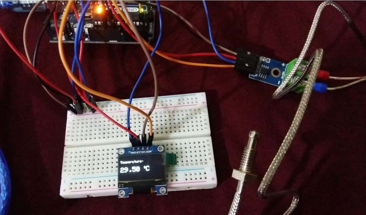
To see the demonstration of the above code, upload the code to Arduino. But, before uploading code, make sure to select the Arduino fromTools>Boardand also select the correct COM port to which the Arduino board is connected fromTools>Port.
One time the code is uploaded to Arduino, the OLED will start displaying the temperature readings in degrees Celsius afterwards every second.
Video demo:
Other sensors guides with Arduino:
- TCS230/TCS3200 Color Sensor with Arduino
- Rotary Encoder Module with Arduino
- HC-SR04 Ultrasonic Sensor Interfacing with Arduino
- Interfacing Multiple DS18B20 with Arduino: Display Readings on OLED
- DHT11 DHT22 with Arduino
- Interface TMP36 Temperature Sensor with Arduino
- BME280 with Arduino: Display Readings on OLED ( Arduino IDE)
Display Max6675 Thermocouple Readings on 1602 Lcd Arduino
Source: https://microcontrollerslab.com/max6675-thermocouple-arduino-tutorial/